Download our 2022 Product & List Price Catalogue
Training Center
NEWS CONTENT:
New Production Plant in San Donà di Piave
HP COMBI, New Optimized Motor and Drive Package
HPS Series Permanent Magnet Motors - Now Available with NEMA C-Face Output
Become a PTDA (Power Transmission Distribution Association) Member
U.S Energy Efficient Requirements for Electric Motors
Lafert Custom Options
Motor Winding & Insulation Components
SITI Gearboxes - Did You Know?
The Evolution of Efficient Motors
RECENT EVENTS
PTDA INDUSTRY SUMMIT - October 23-25 2025, San Antonio
Lafert Introduces New Production Plant in San Donà di Piave
The new production plant is officially in operation after its formal unveiling at Lafert’s 60th anniversity celebrations in San Donà di Piave, Italy, close to the historic headquarters.
The 130 000 sq foot plant was developed to increase production capacity and meet the growing demand for IE5 Super Premium Efficiency motors, while also providing new storage areas for raw materials and finished products. In this plant alone, Lafert is able to produce up to 1400 pieces per day and can ship 4-5 international containers per week thanks to the internal customs area.
The project began in September 2020 with the aim of building a brand-new manufacturing plant to produce high efficiency permanent magnet motors, specifically intended for pumping applications. The plant was designed and built with extensive automated production capabilities including fully automated production lines. Today the plant employs 50 operators who have been carefully trained to work in synergy with the production lines. The plant delivers maximum comfort in the working conditions of the operators in terms of light, space, services, and other factors that affect the well-being of employees.
In 2022, a photovoltaic system was installed consisting of 762 high-efficiency monocrystalline silicon modules generating 345 kW of power. When fully operational, the photovoltaic system will be able to produce about 380,000 kWh of renewable energy annually, corresponding to the total energy needs of the plant. This reduces CO2 emissions by 154 tons per year and supports Laferts mission to work towards a better future for our planet.
Introducing HP Combi - Packaged PM Motor & Drive Solution
HP Combi is a range of highly efficient motor and variable frequency drive (VFD) packaged solutions which combine industry-leading permanent magnet (PM) synchronous motor technology from Lafert with dedicated drive platforms engineered to deliver maximum energy cost savings and system performance for three application categories – pumps and fans (Combi Flow), automation and motion (Combi Plus) and general purpose (Combi Smart).
- Optimized for increased system efficiency available up to 50 HP
- Plug & Play solution fully dimensioned and configured according to customer needs
- Advanced control electronics for easy commissioning, control and service
- IP66 / NEMA 4X outdoor
- Precise speed control
Designed for both variable torque applications, typically in HVAC, and for constant torque applications such as material handling, air compressors and vacuum pumps.
 Power Transmission Distribution Association
The speed and power of change and transformation is unprecedented in today’s business climate. Technological advances bring about new opportunities and obliterate old business models. Generational turnover shifts everything from work culture and communication styles to attitudes and leadership. Uncertainty governs the day and hampers growth. But still you must keep moving forward.
The PTDA Industry Summit provides you with the tools needed to handle any disruption with an industry-specific focus on current events and economic trends.
This is where the power transmission/control industry comes together to solve problems and innovate throughout the channel. On average, more than 550 delegates—the industry’s top executives representing over 230 companies—network and conduct business at the PTDA Industry Summit.
Register online or download the brochure to register by email, fax or U.S. mail. Follow PTDA on Twitter and search with hashtag #PTDA16IS to be among the first to know!
Enhance your competitive advantage by accessing the many resources to which your PTDA membership entitles you at no additional charge, including:
Market Trend Resources
Industry Formats & Guidelines
Networking Tools
PTDA's LinkedIn Groups
Relationship Management Resources
Executive Management Resources
HPS Series Permanent Magnet Motors
NEMA C-Face Output Available for Footless Mounting
Download the Lafert HPS Series Technical Catalogue
 Hybrid Design for Hybrid Applications
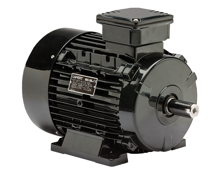
Lafert presents the HPS Series of permanent magnet motors for automated equipment applications where induction motor performance falls short of the mark, or servo motor cost and complexity is impractical. It’s no accident that HPS Series motors are well suited to filling this motor capability gap; the motor construction integrates the cost-effective induction motor stator housing and stator winding with high-performance permanent magnet servo motor rotor technology. The hybrid design is a highly efficient synchronous motor which outperforms induction motors and offers tremendous value for speed control applications. An industry leader in permanent magnet motor technology, Lafert has proudly manufactured HPS Series Motors for twenty years. HPS motors are available from stock with standard power ratings to 50 HP for 230, 460, 575 V input. Mounting options include modular base mouths with or without standarized IEC (B5 or B14), and NEMA (C-Face) flanges.
Reduced Losses, Increased Reliability
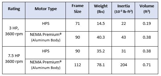
Energy efficiency has not been a traditional performance consideration for motion control applications, but efficiency has direct reliability and performance implications for motors and systems. All HPS Series motors exceed the current requirements for induction motor efficiency, NEMA Premium®, with motor efficiency performance at or above the “Super and Ultra Premium” (IE4/IE5) level. This increased energy efficiency is due to the permanent magnet rotor construction, which reduces the electrical rotor losses to zero. Induction motor rotor losses are defined as the electrical power converted to heat by current flow (I2R) in the rotor, which typically accounts for 10 – 15% of total losses. Eliminating the rotor losses delivers the dual benefit of increasing energy efficiency and reducing the amount of heat generated by the motor. In simple terms: HPS Series motors create less heat per unit of mechanical power delivered to the load. This explains the reduced thermal rise and thermal time constant, and increased maximum ambient temperature and overload capability of HPS Series motors. The industry rule of thumb, which states that each 10°C rise in motor winding temperature reduces insulation life by half, establishes the case for correlation of reduced HPS Series motor losses with longer field service life. With less waste heat to be eliminated from the enclosure, HPS motors require less material volume and surface area to remain cool. Space and weight savings will vary but in the general case reductions on the order of 50 % can be expected in comparison to equivalently rated induction motors.
High Performance, Without Feedback
Energy efficiency has not been a traditional performance consideration for motion control applications, but efficiency has direct reliability and performance implications for motors and systems. All HPS Series motors exceed the current requirements for induction motor efficiency, NEMA Premium®, with motor efficiency performance at the “Super or Ultra Premium” (IE4/IE5) level. This increased energy efficiency is due to the permanent magnet rotor construction, which reduces the electrical rotor losses to zero. Induction motor rotor losses are defined as the electrical power converted to heat by current flow (I2R) in the rotor, which typically accounts for 10 – 15% of total losses. Eliminating the rotor losses delivers the dual benefit of increasing energy efficiency and reducing the amount of heat generated by the motor. In simple terms: HPS Series motors create less heat per unit of mechanical power delivered to the load. This explains the reduced thermal rise and thermal time constant, and increased maximum ambient temperature and overload capability of HPS Series motors. The industry rule of thumb, which states that each 10°C rise in motor winding temperature reduces insulation life by half, establishes the case for correlation of reduced HPS Series motor losses with longer field service life. With less waste heat to be eliminated from the enclosure, HPS motors require less material volume and surface area to remain cool. Space and weight savings will vary but in the general case reductions on the order of 50 % can be expected in comparison to equivalently rated induction motors.
Leveraging Lineage, Learning More
In addition to synchronous operation, HPS Series motors inherits two characteristics from the servo motor with performance implications for motion applications. First, the reduced weight and dimensions of permanent magnet rotors yield higher HPS torque-to-inertia ratios than induction motors. Higher torque-to-inertia ratios are desirable because they supports higher system dynamic response and repeatability. Second, the synchronous motor torque-producing mechanism enables the flat torque curve across a wide speed range and a short-time 300% peak torque capability. Contact us to learn how and why the unique construction and capabilities of HPS Series motors can drive top performance from your next motion control application.
Lafert Custom Options!
The Lafert Group, a leading European Motor Company, is committed to continuous growth by being the global leading manufacturer of custom engineered Electric Motors and Drives with specific focus on Industry Automation, Energy Saving, and Renewables.
Lafert strives to be the ideal source for the Electric Motors and Drives industry through focus on meeting specific customer demands. Mutually beneficial partnerships are developed by continuous process improvements utilising state-of-the-art products and techniques by a skilled, motivated and professional workforce.
Lafert North America can design and build custom motor products that other motor manufacturing companies only dream of. Customers that require reliable, top performing custom Italian manufactured motors should call on Lafert North America to help meet their IEC custom needs.
Motor Operation & Technical Review
Motor Winding + Insulation Components
Everyday terms come into use in the electrical industry, one of which is ‘motor winding’. But what exactly are motor windings, what goes into them and what are their differences?
Here is a look at the various components that make up a motor winding and their importance to design, application and longevity of the motor.
Coil / Winding
When one thinks of a what a motor winding is, the intuitive answer is the copper alloy coils that make up the actual current carrying component of the motor. Let’s start there. The metal making up the wire is generally copper (Element #29 in the periodic table of the elements). Copper has many free electrons in its outer shell (VSEPR theory) and is a relatively common element. Therefore, copper is cost effective when used as a conductor. In fact, the metallurgical makeup of the winding is actually a copper alloy; the alloy being less costly than pure copper without giving up significant performance attributes.
The ‘copper’ wire that makes up the winding is manufactured with a thin coat of varnish applied as an insulator so that adjacent strands of wire may physically be in contact with each other whilst each is still isolated from its neighbour. Together these strands make up a ‘coil’. There are different types of varnish that may be applied. The best currently available is rated for VFD service, and can be identified by the burn test.
Burning a wire intended for Non-VFD rated service will result in a black residue, whereas burning a wire that is designed for VFD rated service will yield a green residue (the green tinge comes from a trace amount of titanium in the varnish recipe). Theoretically, there should be no pinholes in the varnish coating of the wire strands.
In practice however, these are unavoidable and various electrical specifications will generally limit the number of pinholes per linear foot of wire. Thickness of the varnish is critical to the ultimate performance of the motor; it must be thick enough to prevent turn to turn shorts yet thin enough so as not to impede performance.
Stator Core
In the stator core (a stacked pile of laminations made from silicone electrical steel) the first step is to insert a ‘slot liner’ into each of the long hollow slots formed in the punch press on each lamination of electrical steel. In LVM this is usually a ‘Mylar NOMEX Mylar ‘sandwich in the shape of a long ‘U’. It is long enough to run the length of the stator stack plus a bit extra for a ‘cuff’ at either end.
The Mylar provides mechanical strength and shape, the NOMEX sets the temperature rating at 180°C (Class H).
The cuff adds mechanical strength as the coil exits the slot and needs that extra strength to resist grounding at the core edge.
After insertion of the slot liner, the first set of coils lays on the bottom of the slot, a centre stick is placed over that group and a second group of coils lays on top of the centre stick. A top stick seals the cavity and the process is repeated around the circumference of the motor core. To separate phases outside the core properly, a phase separator is used (Nomex).
The purpose of adding all these components is to isolate each strand, each coil, and each phase.
As the coil insertion is completed, the next step is to use a lacing material to tie the structure into place, while making certain that the coils are positioned and flared correctly, as not to touch the frame or bearing brackets. The lacing material is usually a heat-shrink product which becomes even tighter as the motor is baked in the oven to cure the non-hydroscopic varnish.
The idea after 2-3 varnish applications and bakes, is to solidify the windings into a solid mass and to displace any moisture or air gaps in the winding properly. As a variation on the theme, the lacing is tied in a more intense pattern on VFD rated motors, interconnecting as many coils as practical and creating a distinct ‘diamond’ pattern on the lacing.
The final step in the wind shop for most LVM is the ‘dip and bake’ process where the LVM core + coil + frame assembly is dipped into a non-hygroscopic varnish and cured in a temperature controlled oven, a process which may be repeated depending on frame size (volume) and manufacturer.
When the motor core emerges from the oven in the last round, the combination of the materials, the lacing and the varnish make for a very solid mass. The VFD rated motor with it’s intense lacing may ‘sing’ in service, the windings flexing and vibrating at the speed of sound at the core edge, the lacing and varnish working to hold it all in place as it wants to move.
‘Signing‘in motor technology is not a good thing; a shortened life is the result as many non-VFD rated motors shall attest when applied on a VFD controlled system. There are many variations on the general theme, the nuances may be or may not be critical to use and will vary in importance by application. One of the most crucial aspects is the use of VFD control. In any event, the purpose here is to offer a basic understanding of the components and materials. For a further explanation, please feel free to consult your trusted source.
SITI Gearboxes - Did You Know?
SITI Gear is an Italian manufacture of high-quality and diverse industrial gear reducers represented by Lafert North America.
SITI Gear proudly presents the following did you know…?
Did you know there are two primary considerations for selecting the correct gear oil for an application?
Gear Speed
Viscosity, by definition, is an oil's resistance to flow and shear.
In contrast, low speed applications such as shredders and winches are associated with high loads, therefore tooth engagement have longer contact times. These conditions require higher viscosity oils. EP (extreme pressure) additives may be required if the loads are very high.
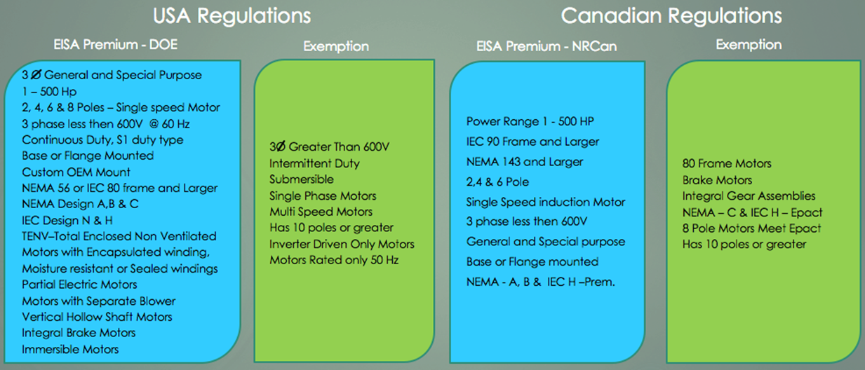
U.S. Energy Efficient Requirements for Electric Motors
Did you know that new energy efficiency regulations for induction (AC) motors sold and installed in the United States were introduced on June 1st, 2016?
The new regulations expand the scope of the Energy Independence and Security Act (“EISA”) of 2007 which required most induction motors sold after December of 2010 to meet NEMA Premium® efficiency levels. The expanded efficiency requirements are referred to as either the “EISA Expansion” or the “Integral Horsepower Rule”, the U.S. Department of Energy “Final Rule” passed into law on May 29th, 2014. The “EISA Expansion” does not define a new standard for motor energy efficiency, but instead expands the established requirement for NEMA Premium® efficiency to a broader range of induction motor types. Significant expansions include the addition of 6- and 8-Pole motors, continuous-duty brake motors, immersible motors and IEC Frame 100 motors. The expanded regulation closes many “loopholes” in the EISA legislation and consequently most induction motors sold after June 1st, 2016 in the U.S. must (by law) meet or exceed the applicable NEMA Premium® efficiency level. Why make the change? It’s a matter of dollars and sense. The DoE estimates direct operational cost savings from increased efficiency “EISA Expansion” motors purchased during the period 2016 – 2045 to fall somewhere between US$18.2 – 41.4B. To accommodate these new regulations Lafert North America now offers an expanded AMPH Series of motors, which carry UL Energy Verified marking to certify NEMA Premium® efficiency.
Additional information regarding the recent “EISA Expansion” can be found in the excellent presentation available here, provided by the Electrical Apparatus Service Association (EASA).
THE EVOLUTION OF EFFICIENT MOTORS
Did you know that the history of electric motors traces back nearly 200 years? Advancements in motors continue at present, although the basics were laid during the 1800s. Much has changed over the years in the evolution of motors; one main factor that has recently been enforced is motor efficiency levels. The Department of Energy (DOE) has regulated the energy efficiency level of electric motors since 1997. Electric motors convert electrical energy to rotating mechanical energy. When operating, the electrical energy is transferred as useful mechanical energy to some driven device such as a fan, pump, blower, compressor, or conveyor.
The Energy Policy and Conservation Act (EPCA), as amended by the Energy Independence and Security Act of 2007 (EISA 2007), covers three broad categories of electric motors: general purpose, definite purpose and special purpose.
These broad categories include a variety of motors including single-speed, continuous-duty polyphase motors with voltages not greater than 600 volts; motors with or without mounting feet; motors built in a T- or U-frame; motors built with synchronous speeds of 3600, 1800, 1200, or 900 rpm (two, four, six, or eight poles, respectively); National Electrical Manufacturers Association (NEMA) Design B motors from 1 to 500 horsepower, NEMA Design A and C motors from 1 to 200 horsepower; and motors that are close-coupled pump or vertical solid-shaft normal thrust motors.
With its most recent final rule, with a compliance date of June 1, 2016, DOE is expanding the regulation and establishes energy conservation standards for a number of different groups of electric motors that DOE has not previously regulated. This amended standard will save approximately 7 quads of energy and result in approximately $41.4 billion in energy bill savings for products shipped from 2016-2045. The standards will avoid about 395 million metric tons of carbon dioxide emissions.
- https://www1.eere.energy.gov/buildings/appliance_standards/product.aspx/productid/50
Compliance: Design Changes, Testing & Certification
To comply with the new regulations, motor manufacturers will need to change original motor designs significantly. Since additional active materials, like copper and steel, will be needed in motor designs to increase efficiency, the overall cost of motors will likely increase. Changes in manufacturing tooling to build more efficient designs may also be required. Non- recurring engineering may also drive costs higher as motor designs will need to change to achieve these higher efficiency levels.
With the increasing efforts to reduce product costs, it is common for equipment manufacturers and plant buyers to source motors for their equipment from low-cost regions. Motor manufacturers in these regions may not be familiar with the new federal requirements, which may result in negligence on the issue of compliance. Today, the equipment user or specifier must be proactive to ensure the manufacturer has a Compliance Certificate number (CC#). If the manufacturer does not have a CC#, the equipment specifier should contact the motor manufacturer to seek compliance before using those motors.
- Pumps & Systems Magazine
EISA - Premium Efficieny Regulations - 2016
What type of motors need to comply?
56 frame – 3 phase enclosed ≥ 1HP (IEC Equivalent = 80 Frame)
IEC 100 Frame – Previously missed in standard, now included
Special Shafts and Flanges or Base - (Including JP/JM/HP/LP)
Partial motors (But not Rotor and stator component sets)
Brake motors (Integral or removable)
Gear motors - If it meets the definition of Partial motor or can be removed from the gear as a whole motor
Totally enclosed non-ventilated (TENV) electric motors
Immersible electric motors
Electric motors with separately powered blowers
Electric motors with encapsulated windings
Electric motors with moisture resistant windings
Electric motors with sealed windings
Electric motors with sleeve bearings
2014 EISA Increased Coverage
U-Frame motor
Design C motor
Close-coupled pump motor
Vertical solid shaft normal thrust motor (tested in a horizontal configuration)
8-pole motor (900 rpm)
Polyphase motor with voltage no more than 600 volts (other than 230 or 460 volts)
LV Design B (also Design A ) Motors to 201 HP – 500 HP
DOE Integral Motor Regulation Site: http://www1.eere.energy.gov/buildings/appliance_standards/product.aspx/productid/50
Quick Reference Guide
Data and information included on the above “Reference Guide” is for illustrative purposes only and is not to be considered an official document.
The Future is NOW for Lafert...
Lafert has developed and is now stocking an innovative range of High Performance Motors (HP) PM Motors (Permanent Magnet), achieving IE4 Super Premium Efficiency levels, that offer improved efficiency and reduced operating costs. This uniquely engineered product combines the electrical design of Brushless Servomotors with the mechanical design of AC Induction Motors, resulting in the development of a compact motor, robust and efficient; Ideal for energy saving and renewable energy applications.
Energy Savings Comparison
The Following “Energy Savings Comparison” illustrates the cost savings (Euros) in operating a 10HP, 4 pole motor. In the following example, the calculation is done over a 3500 h/year operation; the yearly consumption savings in using a premium Efficiency IE3 Design motor over an IE1 “Standard Efficient” would be of 222.90 Euros. Furthermore, higher savings can be achieved (330.90 Euros) when using a Super Premium Efficient motor (IE4) which are now in stock at Lafert North America. (the below comparison is in Euros using 0.15/kWh average cost – please check your local energy cost for accurate savings calculation).
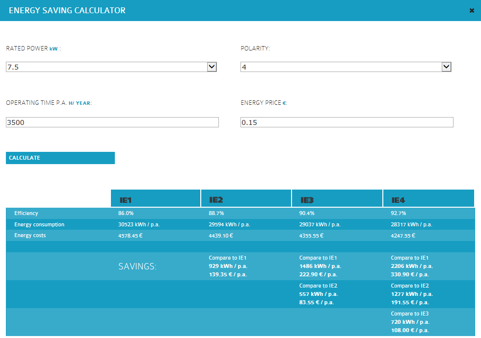
Read more about IE4 (Super Premium Efficient Motors)